Serial Call and Response w/ Buttons (Digital Input)
Sections:
Introduction
If we want Arduino and Touchdesigner exchange messages back and forth, one way to exchange information is with a Call and Response. Essentially we are telling them to take turns exchanging information. We’ll write code that tells arduino to print sensor values to Touchdesigner, but only if Touchdesigner has first sent a byte to arduino. We later tell Touchdesigner to respond to Arduino, writing out bytes if it has received values. In this way they will exchange information (bytes) evenly without either ever sending before the other is ready to receive.
This example shows the necessary python scripts, DATs, and CHOPs to set up Serial Communication with an Arduino. This example uses the the free version of TouchDesigner 2022.31030 and the Arduino Nano 33 IoT.
Arduino Circuit
For this example I’m using a circut with 3 pushbuttons as my digital inputs. This can be adjusted for any number of digital inputs. The circut uses the following components:
- Arduino Nano 33 IoT
- Solderless breadboard
- 3 pushbutton switches
- Hookup wire / jumper wire
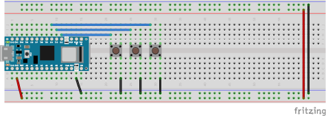
Arduino Code:
If we want Arduino and Touchdesigner exchange messages back and forth. We’ll write code that tells arduino to print sensor values to Touchdesigner, but only if Touchdesigner has first sent a byte to arduino. We later tell Touchdesigner to respond to Arduino, only if it has received values. In this way they will exchange information evenly without either ever sending before the other is ready to receive.
To begin, let’s set up variables for our sensor values:
int sensor1;
int sensor2;
int sensor3;
Next inside of your setup() Use Serial.begin() to start communication at a baud rate of 9600. Remember the baud rate, it will be used later in your touchdesigner network.
void setup(){
    Serial.begin(9600);
    pinMode(2, INPUT_PULLUP);
    pinMode(3, INPUT_PULLUP);
    pinMode(4, INPUT_PULLUP);
}
Inside of your loop() read your sensors using analogRead():
void loop(){
    sensor1 = digitalRead(2);
    sensor2 = digitalRead(3);
    sensor3 = digitalRead(4);
}
After reading your sensors (and while still inside the loop()). Create and if statement that only executes if Serial.available() is greater than 0.
This means whatever you put inside of this statement will only execute if the Arduino has received information on the serial port (from Touchdesigner).
void loop(){
    sensor1 = digitalRead(2);
    sensor2 = digitalRead(3);
    sensor3 = digitalRead(4);

    if (Serial.available() > 0) {

    }
}
If Arduino receives information from TouchDesigner, read that information, remove it from the serial buffer by storing it with a variable int incoming. Then print out the sensor values. Format the communication by separating values with a delimiter (in this case a comma “,”) and ending all communication with a newline character '\n'. The newline will indicate to Touchdesigner that Arduino finished sending all the values for that turn.
if (Serial.available() > 0) {
    int incoming = Serial.read();
    Serial.print(sensor1);
    Serial.print(",");
    Serial.print(sensor2);
    Serial.print(",");
    Serial.print(sensor3);
    Serial.print('\n');
}
Full Code below:
int sensor1;
int sensor2;
int sensor3;

void setup(){
    Serial.begin(9600);
    pinMode(2, INPUT_PULLUP);
    pinMode(3, INPUT_PULLUP);
    pinMode(4, INPUT_PULLUP);
}

void loop() {
    sensor1 = digitalRead(2);
    sensor2 = digitalRead(3);
    sensor3 = digitalRead(4);

    if (Serial.available() > 0) {
        int incoming = Serial.read();
        Serial.print(sensor1);
        Serial.print(",");
        Serial.print(sensor2);
        Serial.print(",");
        Serial.print(sensor3);
        Serial.print('\n');
    }
}
The TouchDesigner Network:
Make the button control your port opening:
Use a button to open and close the Serial port. Create a button component (COMP), make sure the “Button Type” parameter is set to Toggle Up. Connect it to a null CHOP.
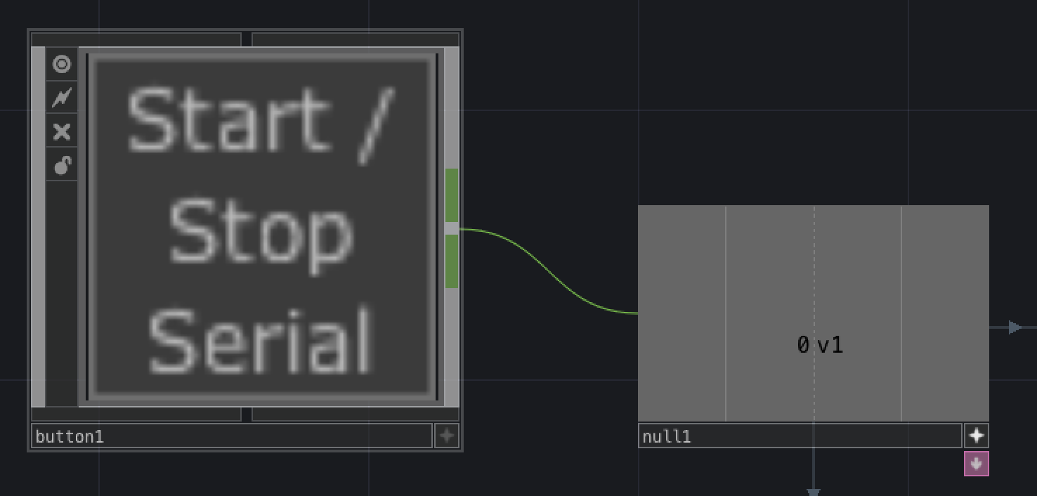
Make the null active and export it to the “Active” parameter of the serial DAT. Then make your button component active and click it to see if the serial DAT toggles on and off.
Send a byte using a script:
Create a CHOP Execute DAT.
The CHOP Execute DAT is designed to trigger specific functions whenever the target CHOP channel values have exhibited any of the parameter changes listed:
Off to OnWhile OnOn to OffWhile OffValue Change
For this case we will only use Off to On.
Make sure the Off to On parameter is enabled. (A toggle button will only change from 0 to 1 and back) Also make sure the CHOPs field refers back to the name of the null that your button is connected to, otherwise it won’t know what component should be controlling the communication. In this example null1 is the CHOP connected to the button.
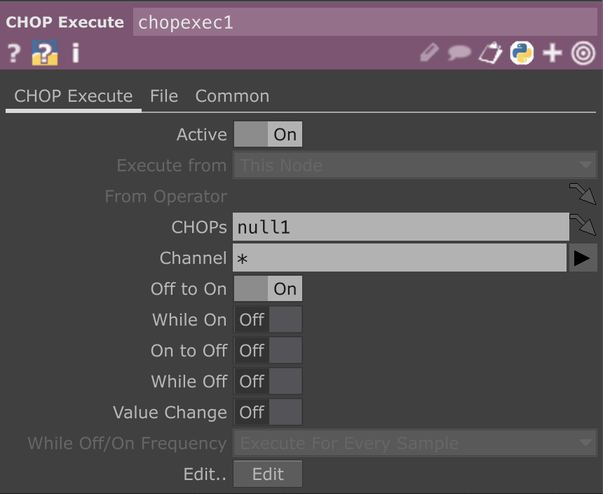
Make the chopExec DAT Active and write a python script that will execute when the button goes from off to on. The code below will send one byte (the character ‘x’) to Arduino when the button is clicked to the on position. Set the terminator option to ‘=’ to only send the specified byte and no extra characters. See the serial DAT reference for more info.
def onOffToOn(channel, sampleIndex, val, prev):
    op('serial1').send('x',terminator='=')
    return
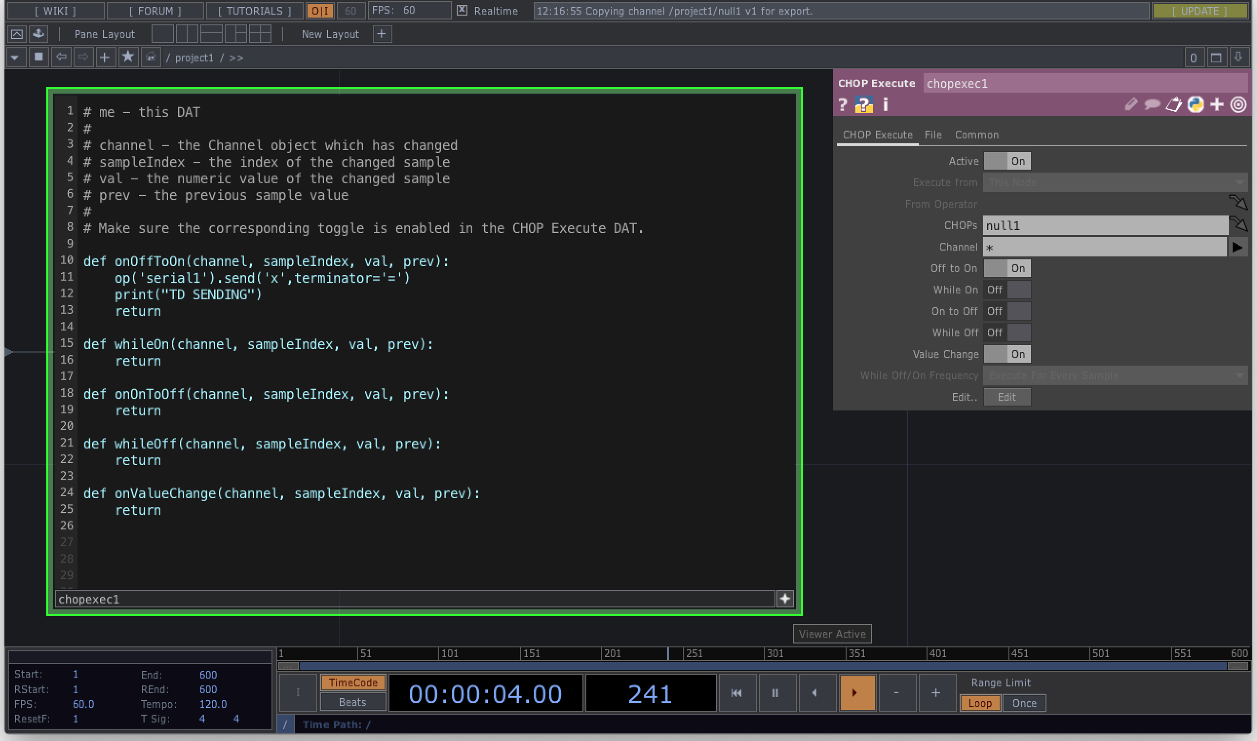
Once this is set up, your button will now be configured to open and close the serial port, and initiate communicaton with the Arduino.
Serial DAT: Receive data
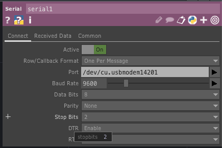
Click on the serial DAT. Set the parameters to read incoming information as such:
Row/Callback Format: “One Per Message”Port: Portnames will differ by computer, it should match what you see in your Arduino IDE (e.g. COM4, usbmodem14201, etc)Baud Rate: 9600 (Baud should match your arduino Baud)Data Bits: 8 (Default)Parity: None (Default)DTR: Enable (Default)RTS: Disable (Default)
Send a byte to Arduino
Create a constant CHOP and connect it to a null this will eventually be the value to send back to arduino.
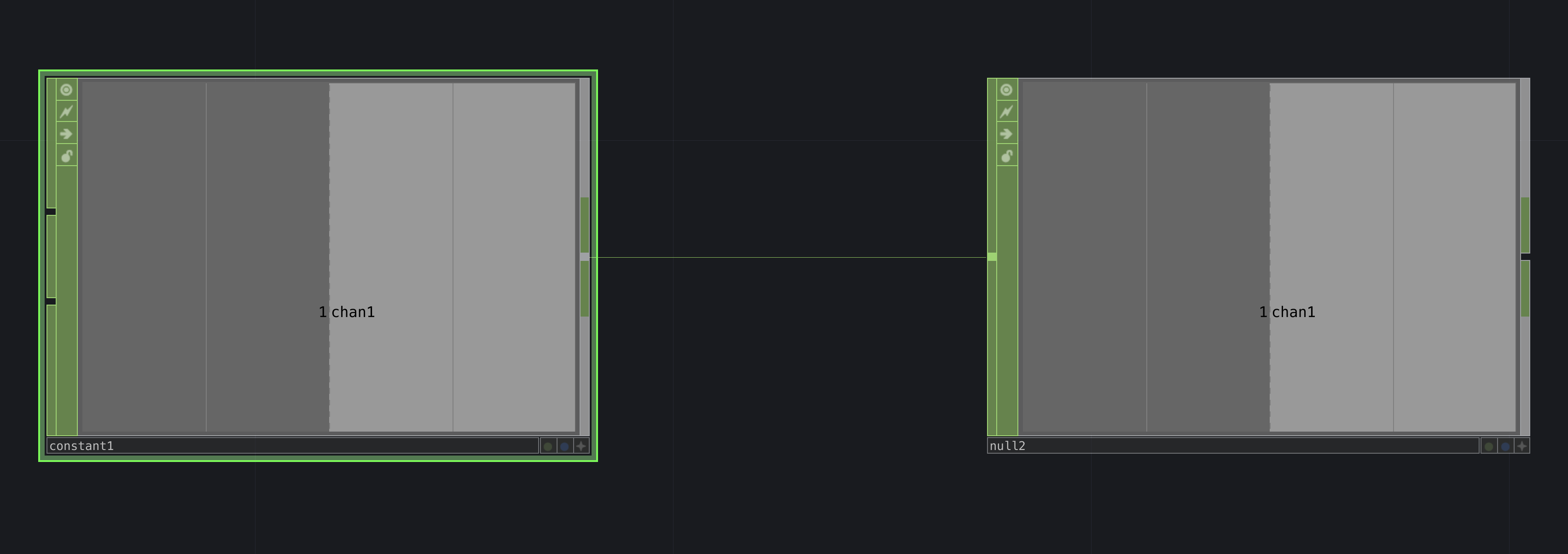
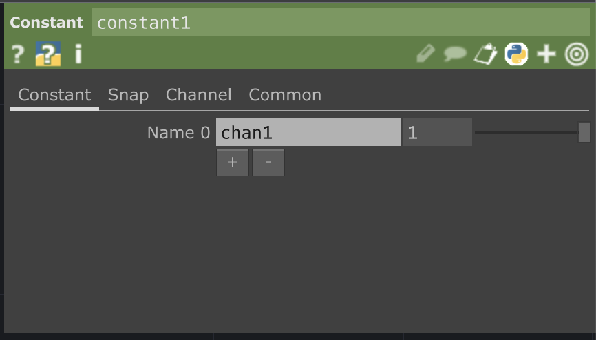
This value can be constant or changing as long as it is between 0-255. It can also eventually be used to control the Arduino’s outputs.
Serial Callback: Send More Data When a Message is Received
Next activate the serial_callbacks scripting DAT.
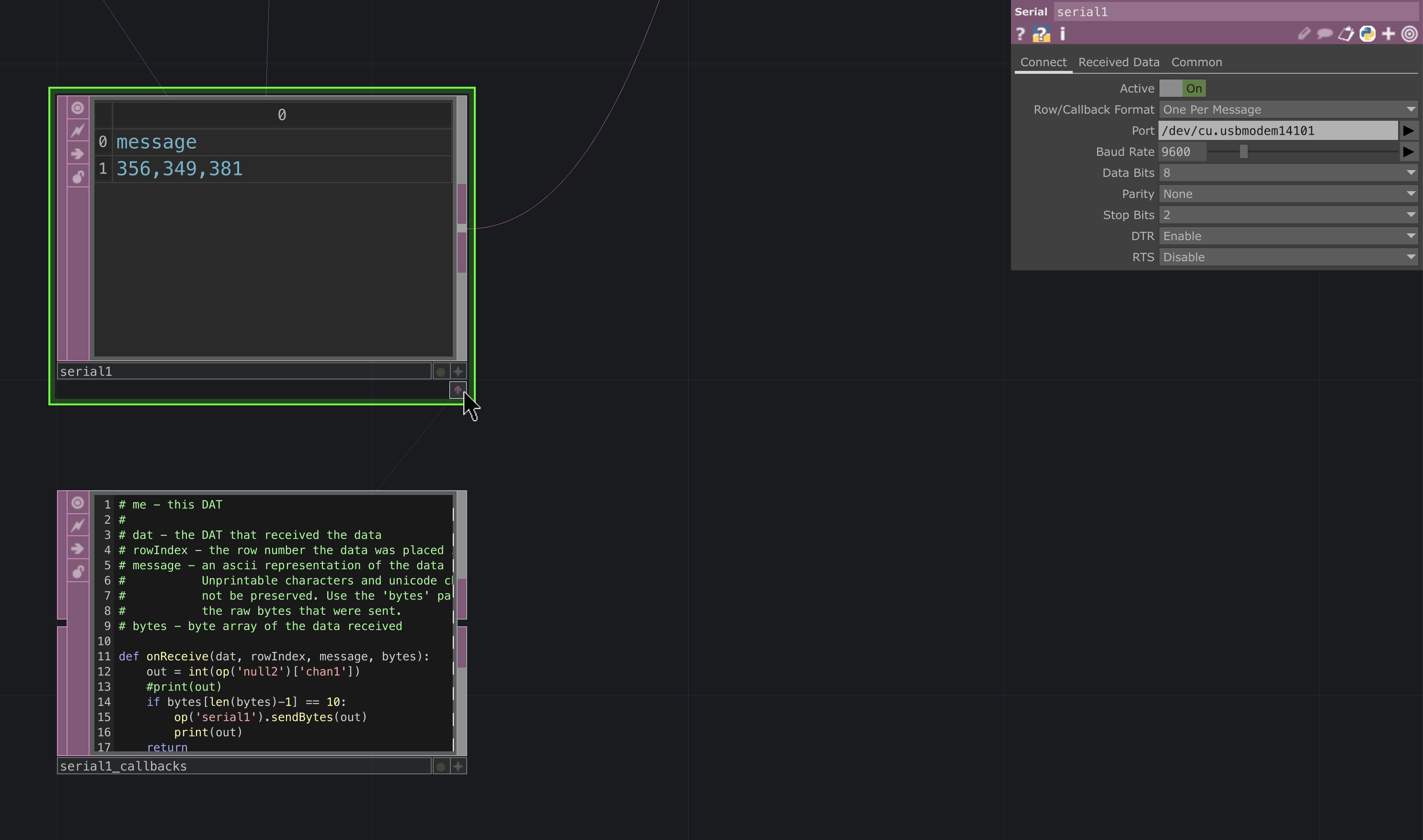
If it is not exposed, click the pink and white arrow icon on the bottom right side of the serial DAT

Make the serial_callbacks DAT active (editable) by clicking it’s + icon and edit the onReceive function. This function will execute each time the serial DAT receives a byte.
Inside the function, make a variable (mine is called “out”) and assign it the constant value thats captured in the null CHOP you just made.
out = int(op('null2')['chan1'])
Next write an if statement to check and see if TouchDesigner has received a complete message from Arduino.
Arduino is printing an ASCII ‘\n’ after it prints all sensor values. In decimal format an ASCII ‘\n’ equals byte 10. ( See the ASCII Table )
Based on how we set up the serial DAT, TouchDesigner will store the received bytes in an array (the bytes parameter of the onReceive function). So if the last byte received by Touchdesigner is equal to 10 that means TD should have received all of the sensor values from arduino. That means we should “request” more values from Arduino, by sending our outgoing byte.
If the last byte is 10, use the serial1 operator to send a Byte to the Arduino:
    if bytes[len(bytes)-1] == 10:
        op('serial1').sendBytes(out)
Full Code for the serial_callbacks DAT:
def onReceive(dat, rowIndex, message, bytes):

    out = int(op('null2')['chan1'])

    if bytes[len(bytes)-1] == 10:
        op('serial1').sendBytes(out)

    return

Make sure the Arduino code is uploaded, and the DATs are up correctly, then click the button to open the port, and your serial DAT should look something like this:
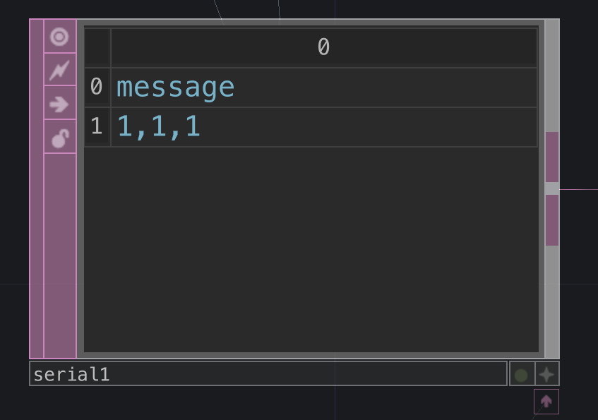
Once the sensor data is coming in reliably we can connect the output of our serial DAT to the input of a convert DAT and use the convert to separate the values.
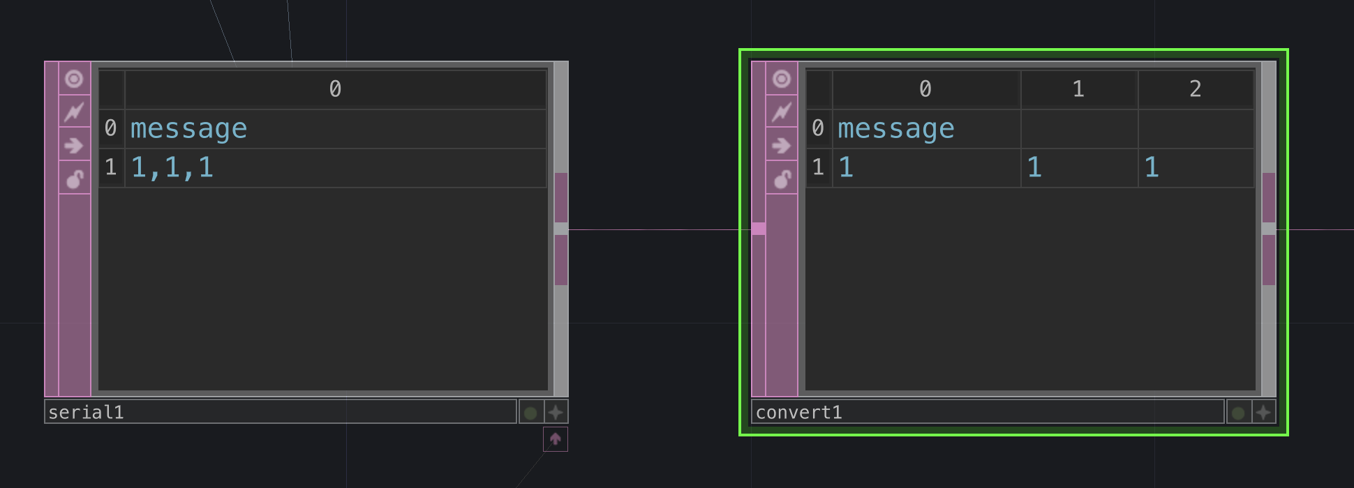
The convert parameters define how you will reformat the incoming values. Make sure that you are converting to a table, this will take values and split them into individual cells. Input a comma ‘,’ in the split cells at field to define which delimiters you are using in between values. You do not need to input ‘\n’, the serial DAT takes care of the ending control character. 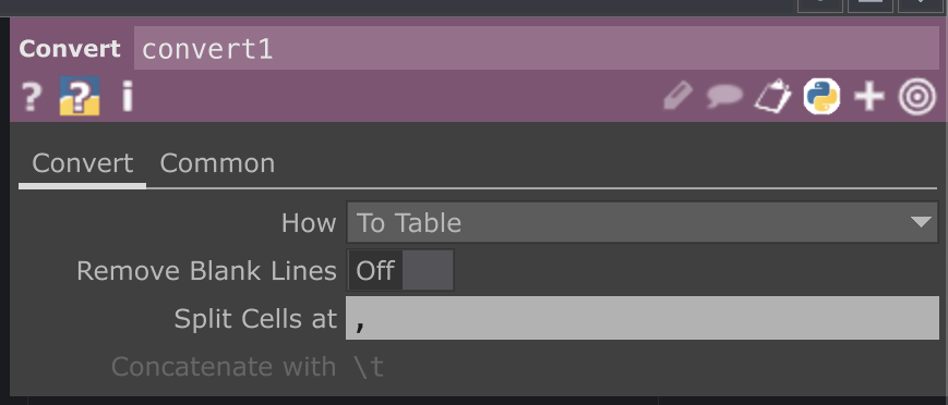
Once we have the values separated, the output of your convert to a DAT to CHOP. This will turn the split DAT values into a channel (CHOP) format. Once you have values in a CHOP you can then export and connect as we have in other examples.
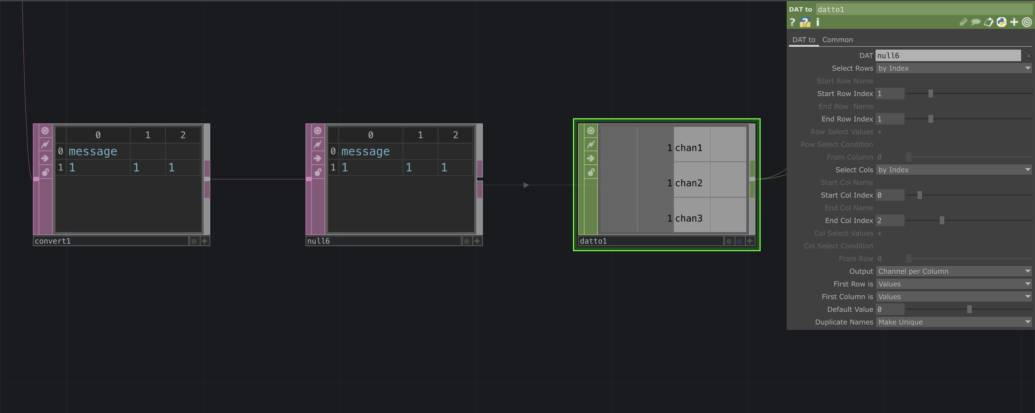
In order to properly sort the information from the convert chop, configure the datto CHOP parameters as follows:
Select Rows: by IndexSelect Cols: by IndexStart Col Index: 0End Col Index: 2 <– (if you have a different amount of sensors use the last index of what you actually have)- ‘Output’ : Channel per Column
First Row is: ValuesFirst Column is: Values

Control Arduino Physical Outputs with TD
Earlier in the tutorial we sent a byte to arduino as a way of controling the flow of communication.
This byte was just a constant value of 1, however we can edit our circuit, code, and network to use that byte of information to control a physical output, in this case, the brightness of an LED.
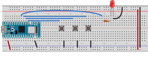
Add an LED to the Arduino Circuit
Connect a 220 ohm (anything from 220 - 1K Ω should work) to digital pin 2 on the Arduino.
Note: Any PWM pin on the arduino. PWM pins are marked with ~ symbol. See the Arduino Nano 33 IoT Pinout Diagram for full detail.
Update the Arduino code
Make a global brightness variable for your LED:
int brightness = 255;
In the setup configure pin 4 as an output using the pinMode() function
pinMode(5, OUTPUT);
In the loop, assign the incoming value to the brightness variable. This is value TouchDesigner is sending to arduino. Use the analogWrite() function and the brightness variable to change the LED’s brightness.
Note: analogWrite() only accepts values from 0-255. At 0 the LED will be off at 255 the LED will appear at full brightness. In the next section we’ll update TouchDesigner to send the correct range of values.
Full Code below:
int sensor1;
int sensor2;
int sensor3;
int brightness = 255;

void setup() {
    Serial.begin(9600);
    pinMode(2, INPUT_PULLUP);
    pinMode(3, INPUT_PULLUP);
    pinMode(4, INPUT_PULLUP);
    pinMode(5, OUTPUT);
}

void loop() {
    sensor1 = digitalRead(2);
    sensor2 = digitalRead(3);
    sensor3 = digitalRead(4);

    if (Serial.available() > 0) {
        int incoming = Serial.read();

        brightness = incoming; // transfer value from TD

        Serial.print(sensor1);
        Serial.print(",");
        Serial.print(sensor2);
        Serial.print(",");
        Serial.print(sensor3);
        Serial.print('\n');
    }

    analogWrite(5 , brightness); // use brightness to fade LED

}
Add a Control Slider
Navigate to the constant and null CHOPs we were using before.
We are going to create a slider to replace the constant and send changing values to Arduino.
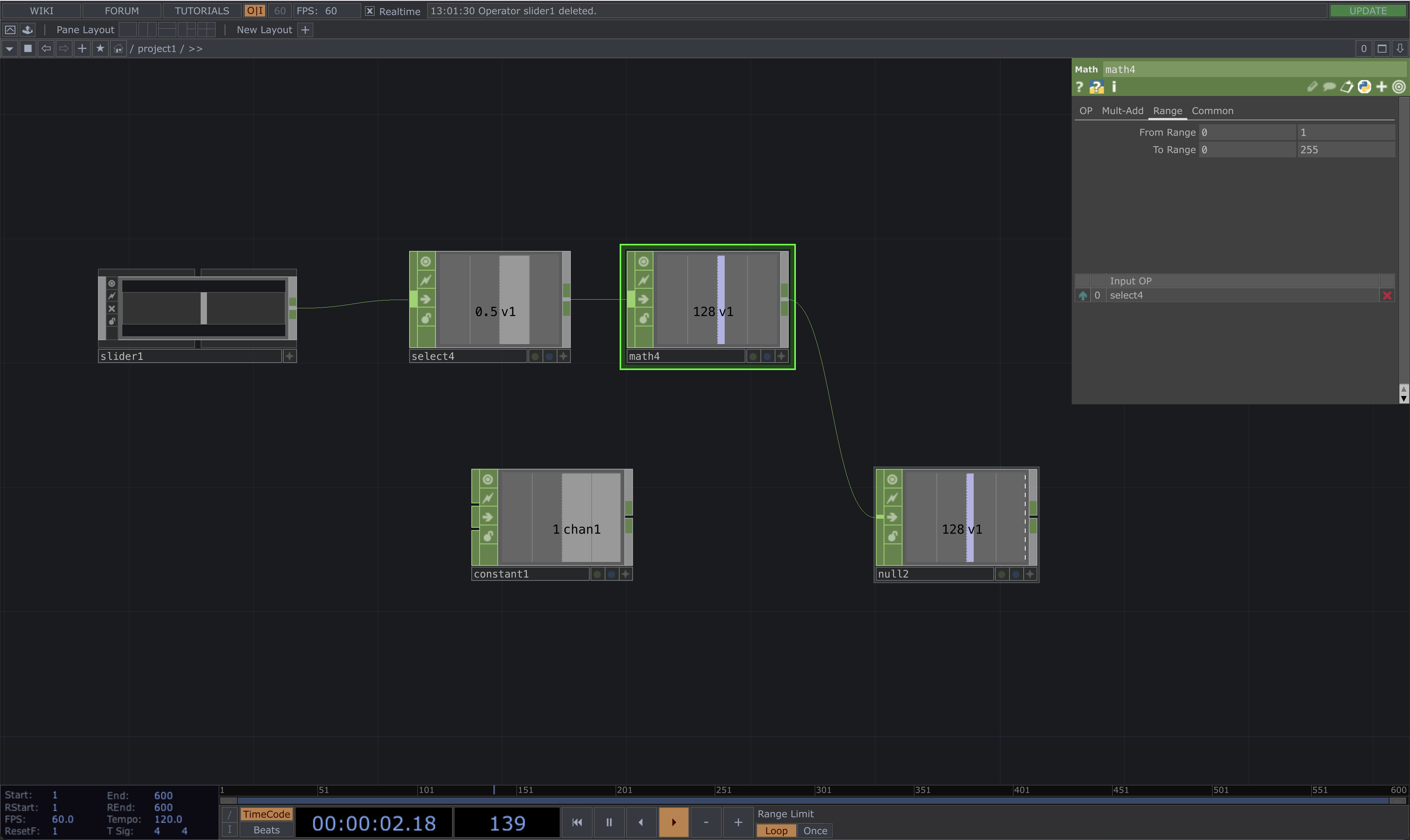
Add a slider COMP and connect it to a select CHOP
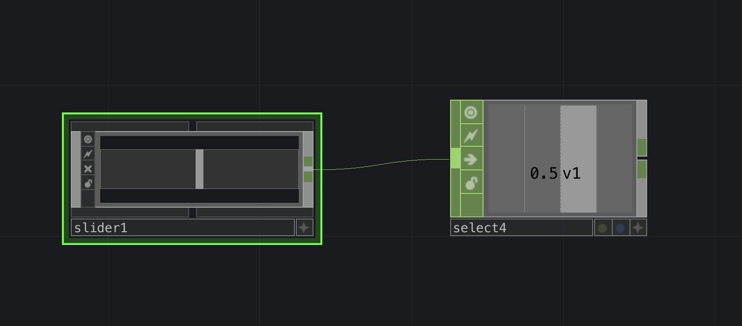
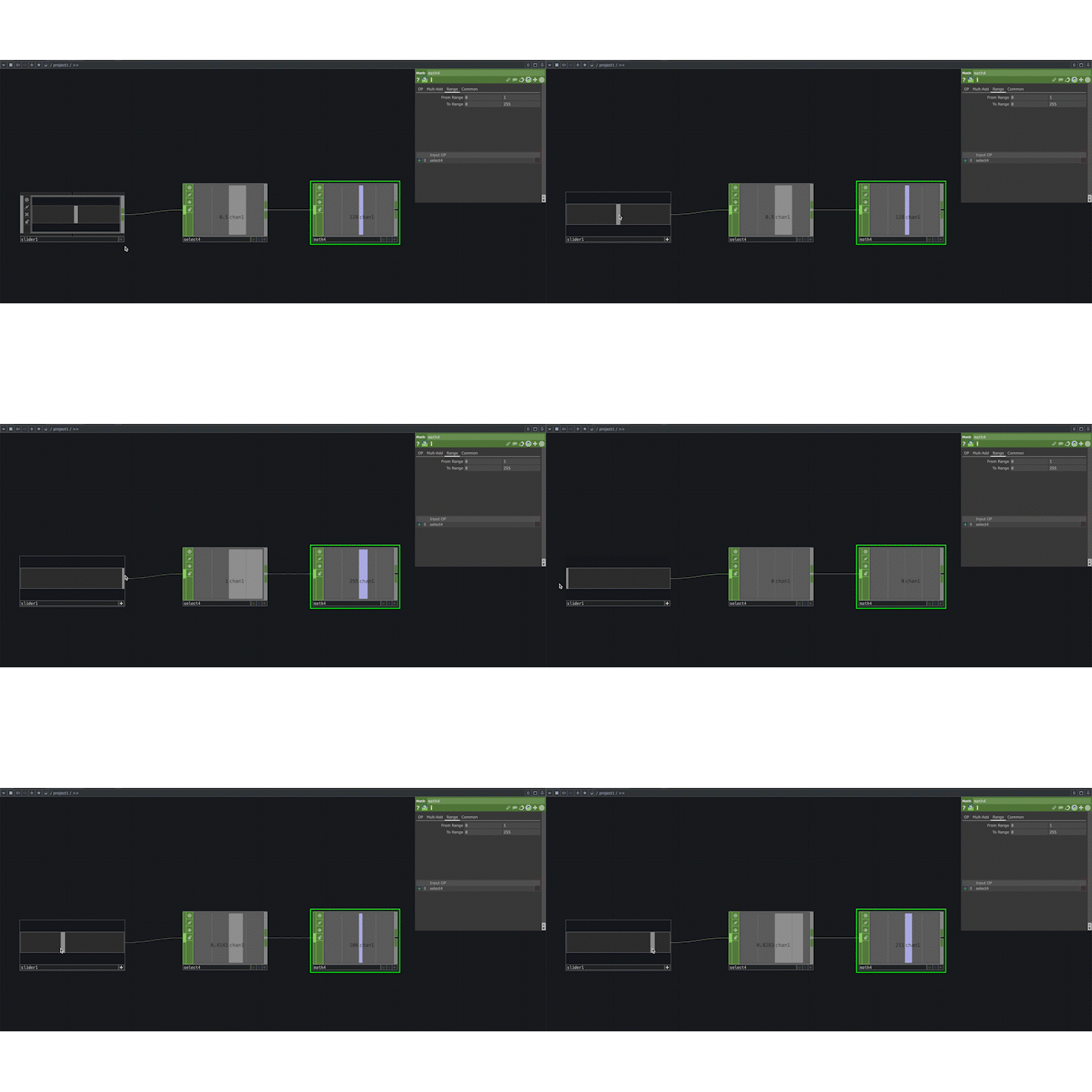
Make the slider active, move the slider and look at the range of values it outputs 
Also notice how the channel name is different from the other CHOP channesl. Our other CHOPs generate channels named chan1,chan2, etc, but the slider has generated a channed with the name v1.
To avoid any conflicts with our previous set up, rename the channel in the select tab of the select CHOP
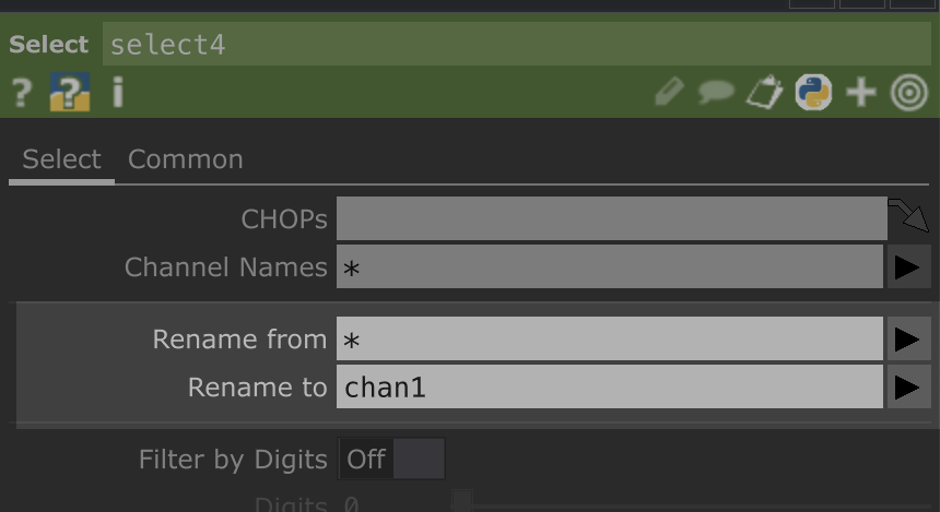
By default TouchDesigner uses normalized values (between 0.0 - 1.0) for nearly all operators. This means if we want to use the slider to control the brightness of the LED we need to map the slider’s range of 0-1 to 0-255 so that it can control the full range of brightness of the LED.
Connect the select CHOP to a math CHOP
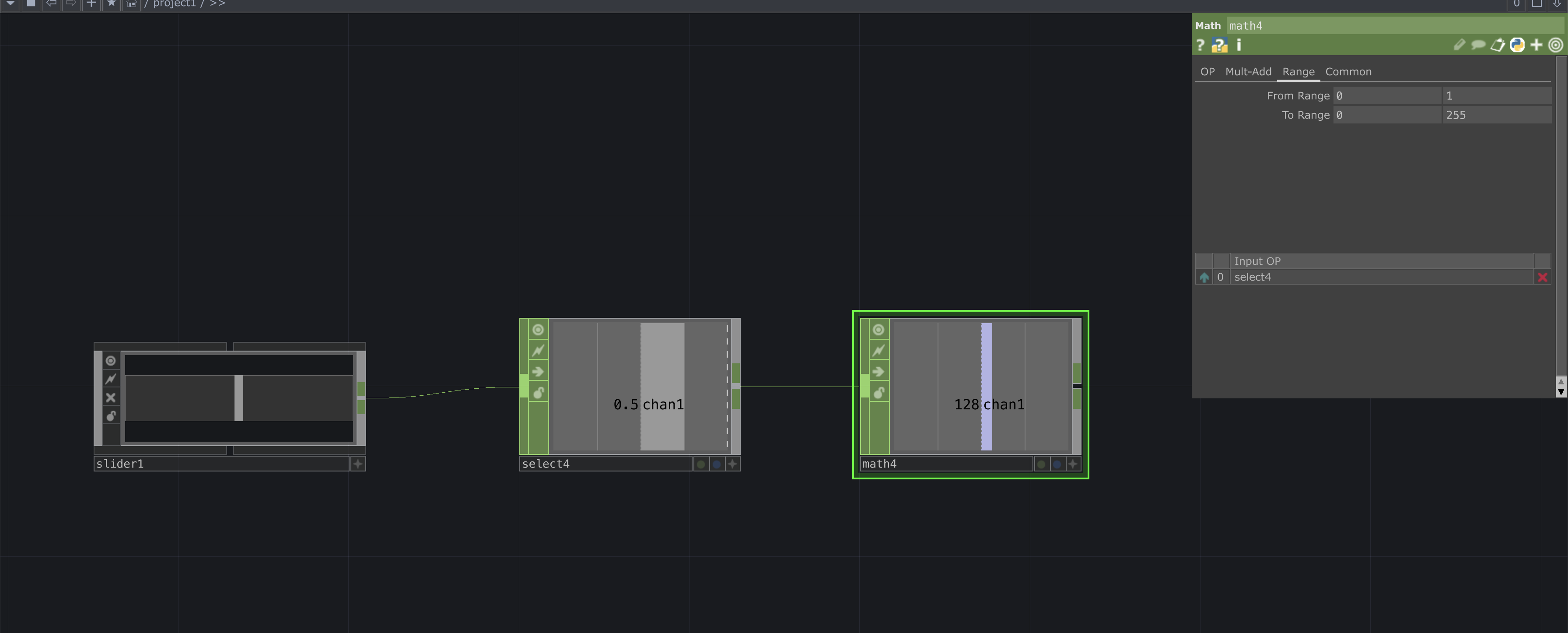
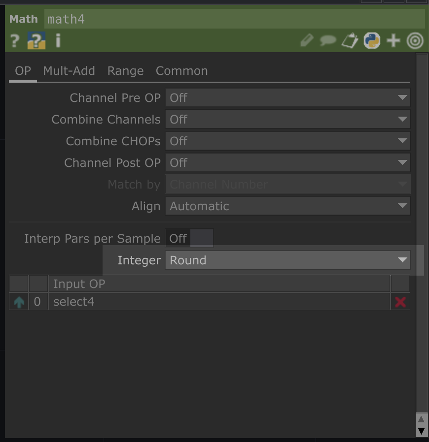
Change the parameters of the math CHOP. First navigate to the OP Tab, and look for the Integer dropdown. Select Round
Navigate to the Range Tab and set the following fields:
From Range: minimum to 0, maximum to 1. This is the incoming range of the slider.
To Range: 0 255 minimum to 0, maximum to 255. This is the outgoing mapped value that we want to send to Arduino.
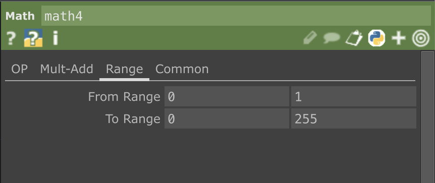
Make slider active and observe how the range changes:
Lastly connect the math CHOP to the null CHOP from earlier. Make sure the constantCHOP from before is also disconnected.
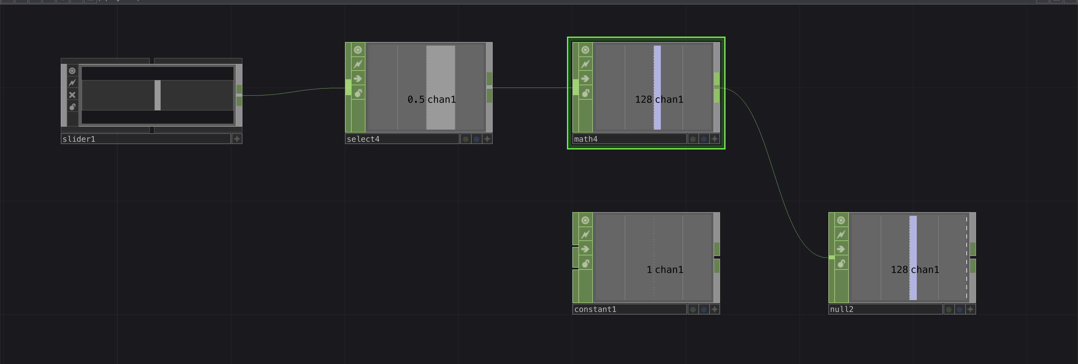
If all is set up correctly you should be able to use the button to connect and disconnect with the arduino. You should see the values being parsed and you should be able to use the slider to change to change the brightness of the LED all at the same time.